Table of Contents
30m Phasing Rx
I recently found an old project that had been left in the junk box unfinished. It's a direct-conversion phasing receiver for 30m.
Inspired by my current binge-listen to the Soldersmoke Podcast https://www.soldersmoke.com/ archives (I'm starting at the beginning and listening to them all.. currently I'm at around Episode 30) I thought I'd restart the project and build it into the planned-for 30m CW transceiver. There's a 5W PA strip that's recently been used in my QRSS MEPT but I'll build a new PA for the MEPT and use the original one for it's original purpose.My New 30m CW QRP TX is finished
I repaired a few broken wires and dry joints and the RX is working. I've checked that the phasing opposite-sideband rejection is working and given it a tweak to check that the adjustments are doing the right things. All looks good.
I'll document the circuit later 
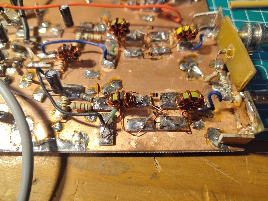
Here are some photos
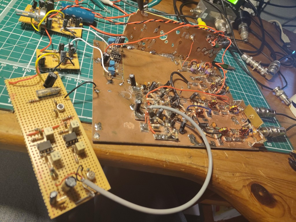
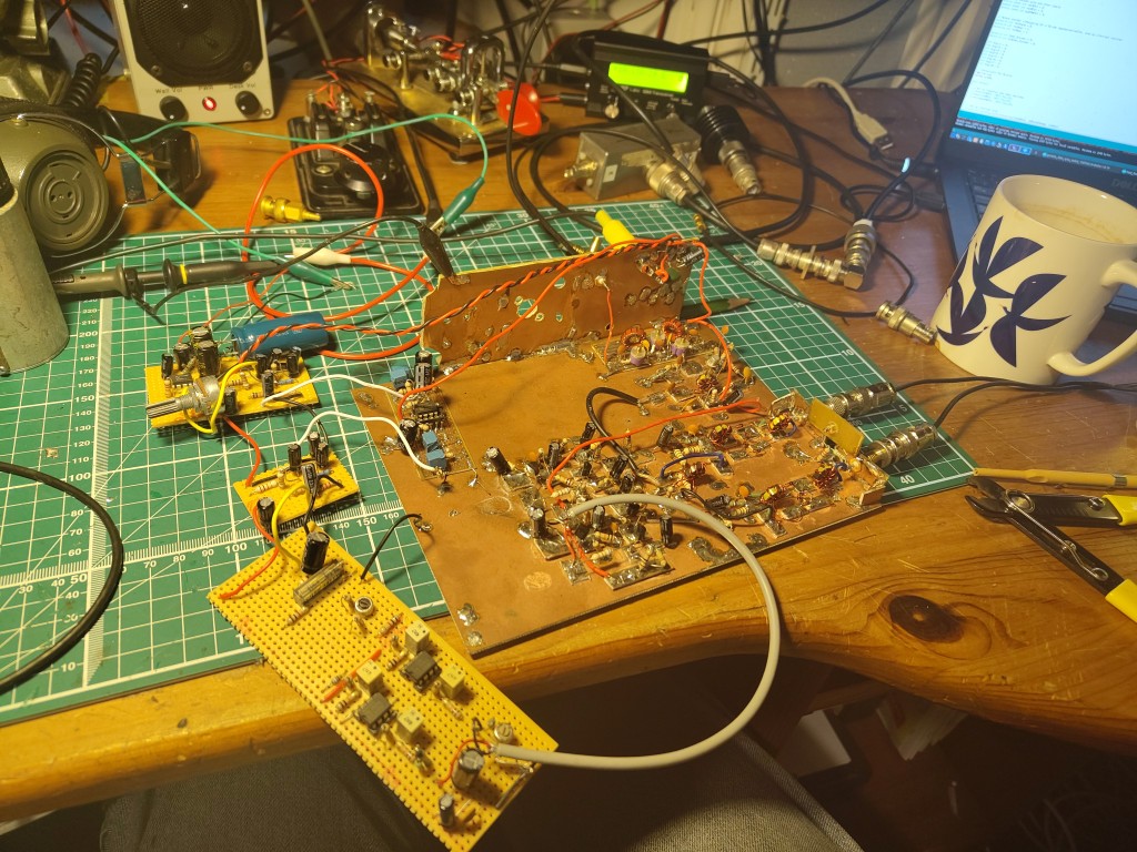
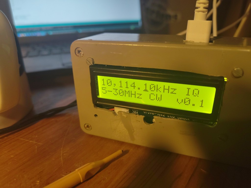
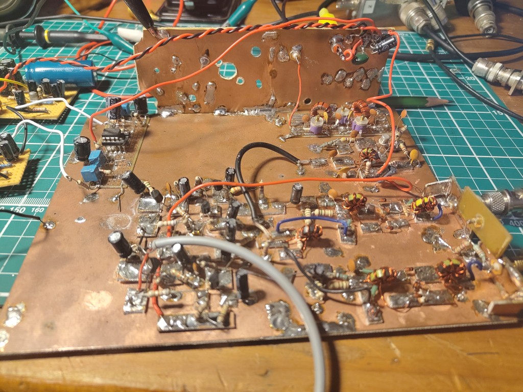
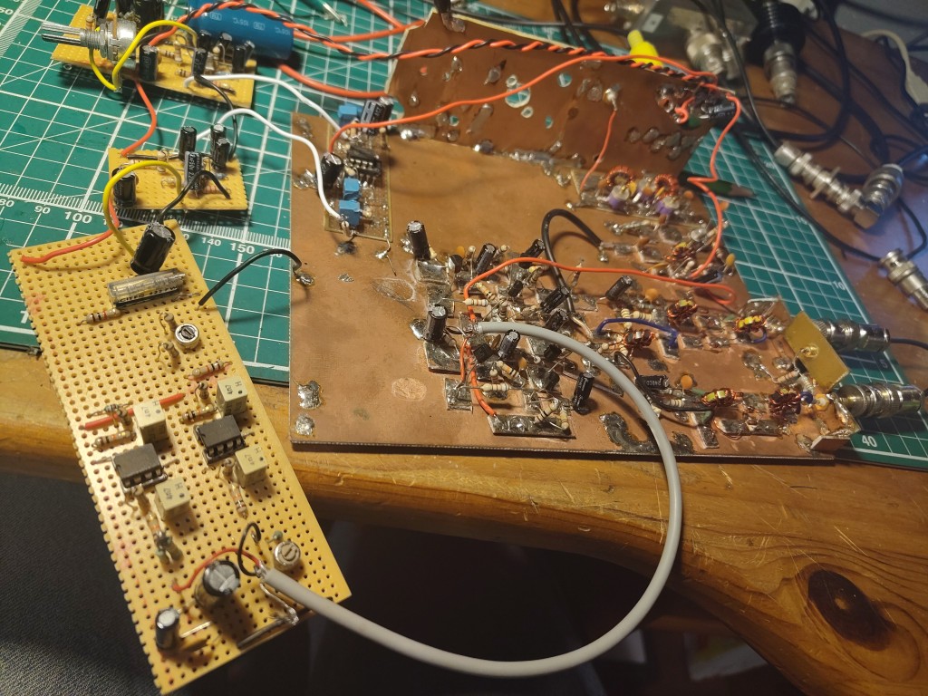
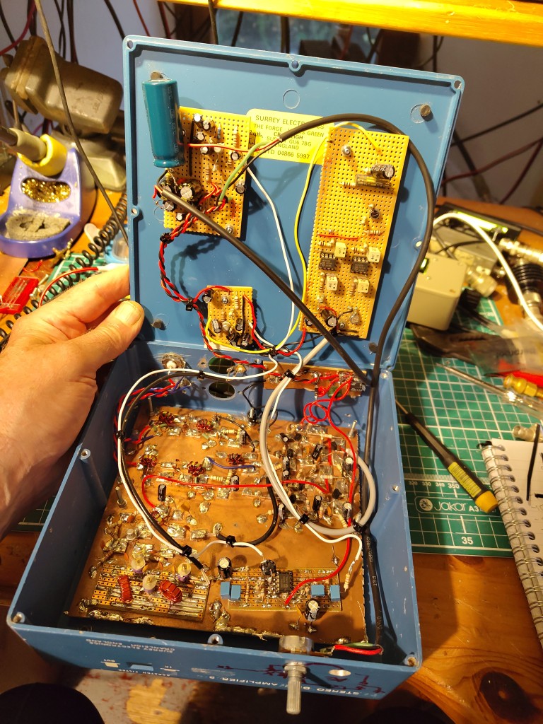
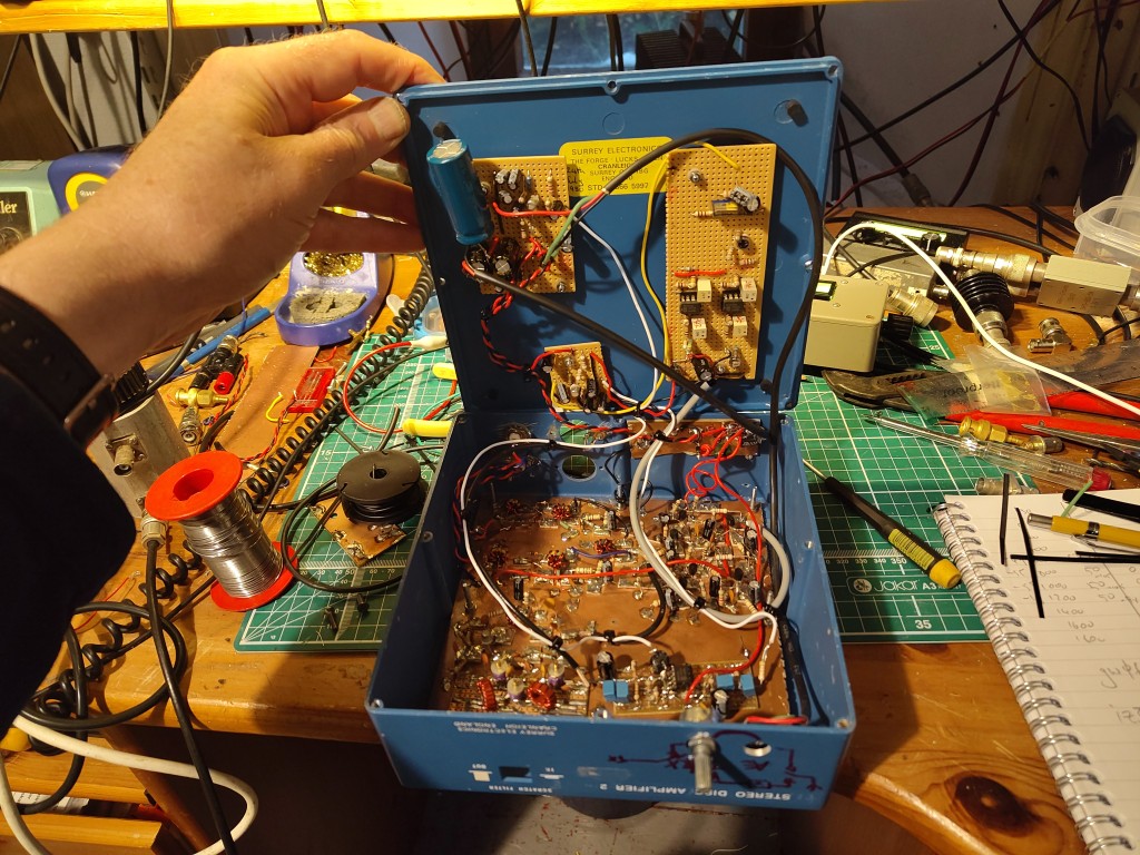
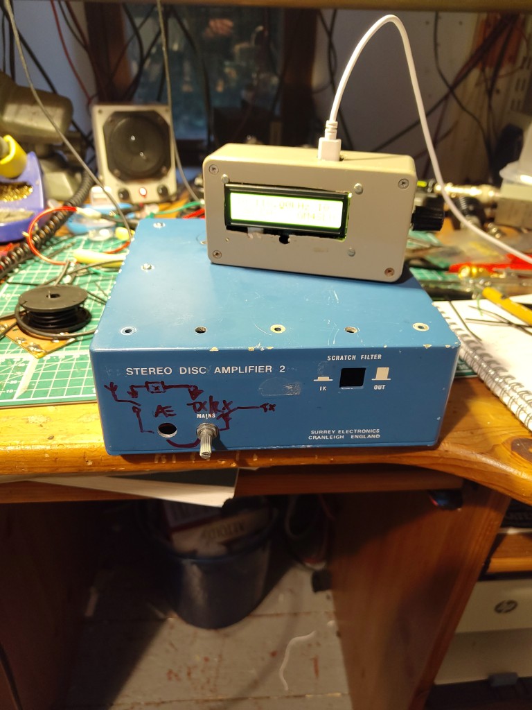
There's a Makertube video of it receiving its first signals…
The design
Coming soon….
Design notes
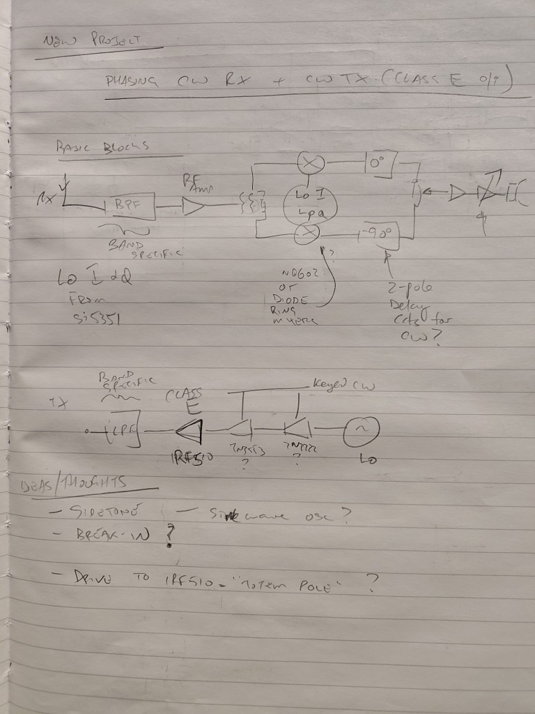
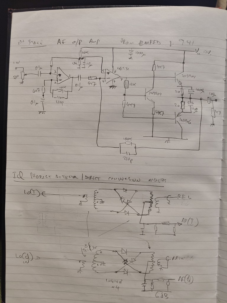
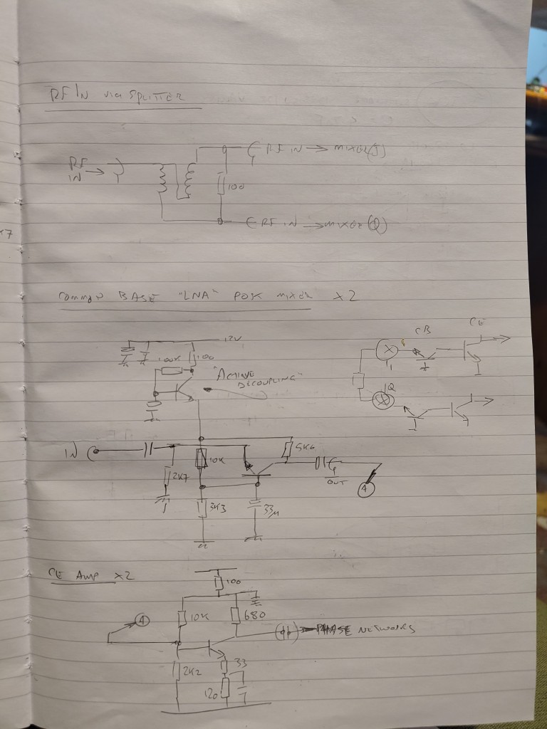
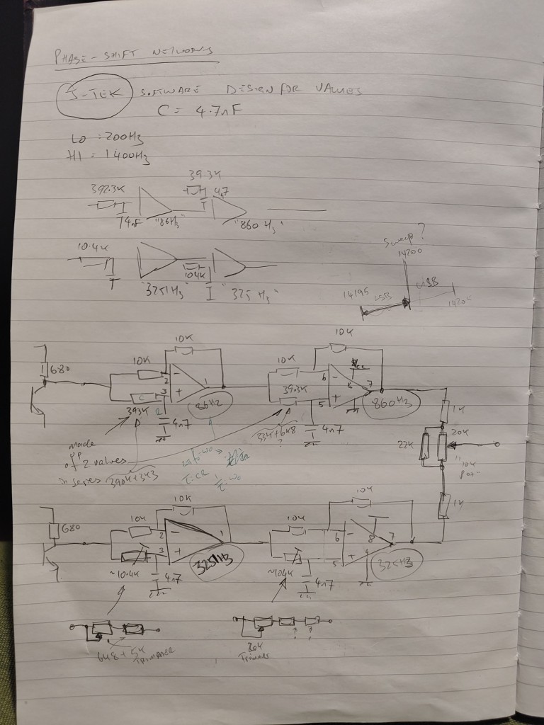
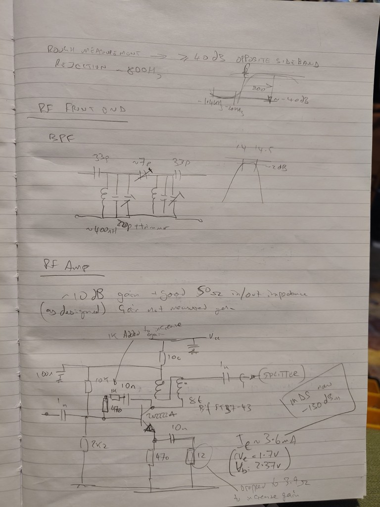
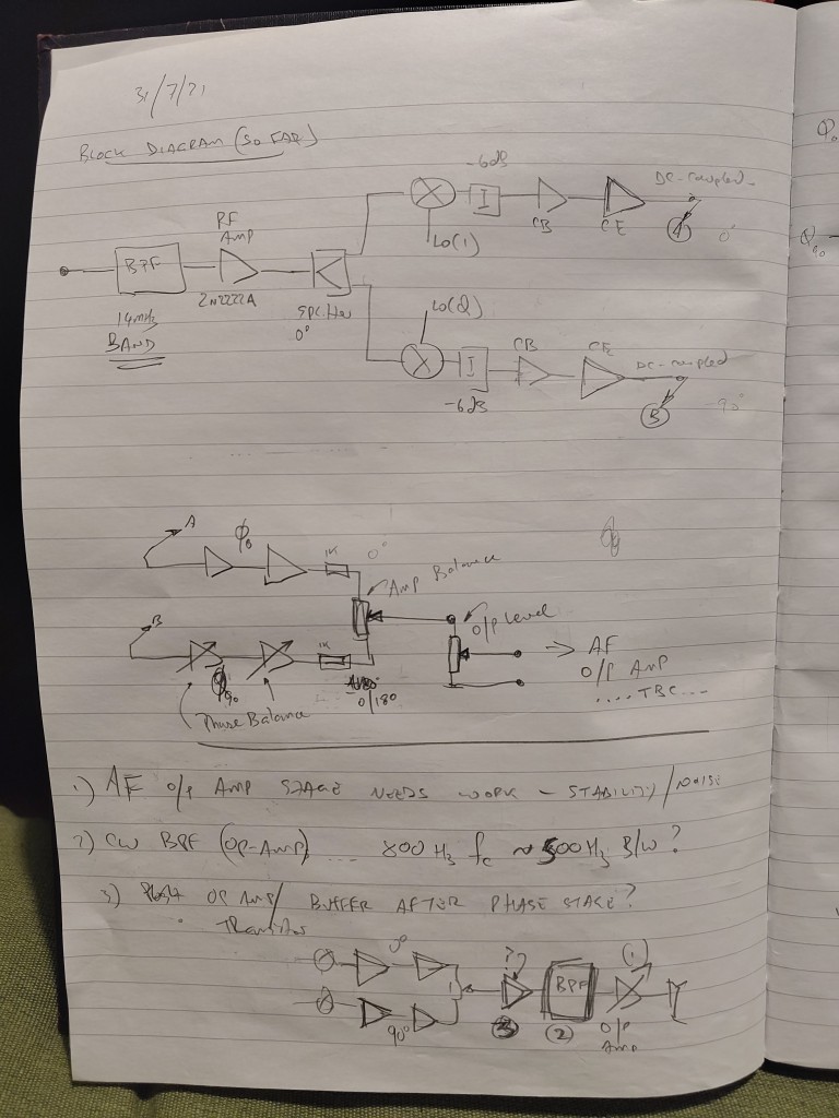
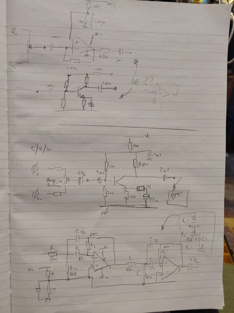
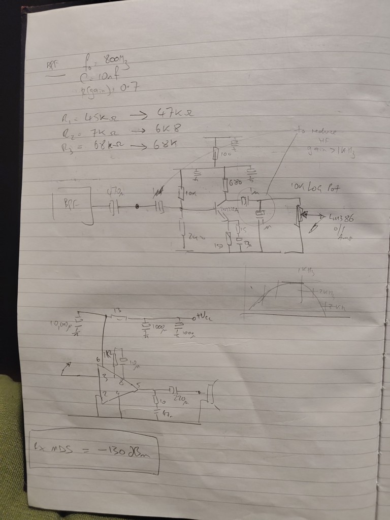
The basic format is
- Band pass filter for 30m
- RF amplifier
- Signal splitter to feed the RF ports of a pair of home-made passive 4-diode balance mixers
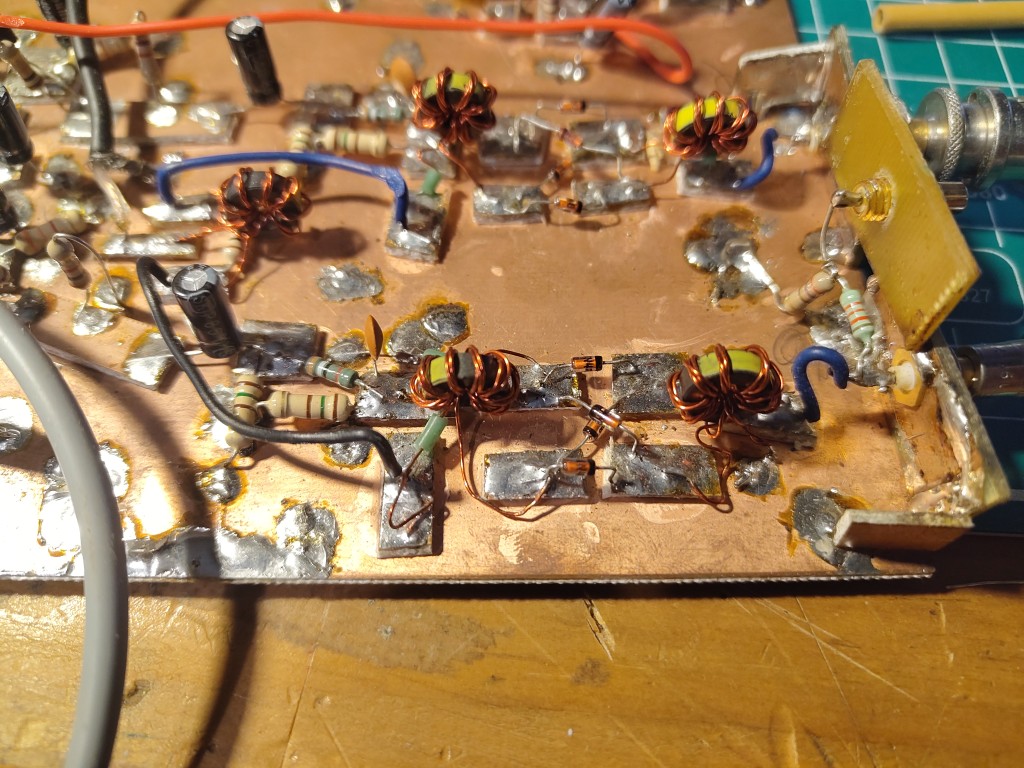
- the 2 mixers are also fed with 90° I & Q local oscillator signals from an arduino/Si5351 IQ VFO
- The outputs of the 2 mixers is a pair of baseband audio signals in quadrature which then pass through the phase-delay circuits
- The 2 paths combine such that the audio from the unwanted sideband is cancelled and audio from the wanted sideband is presented to to an op-amp audio BPF centred on 700Hz.
- Then there's a audio amplifier that can drive a speaker.
Updates
After using it alongside my separate 30m TX while testing the TX I found it very necessary to turn the volume down FULLY before transmitting, otherwise, un-muted, the receive audio is dangerously LOUD… that's fine as long as I remember to turn the volume down…. but after forgetting once, while wearing headphones, I don't dare risk it again!
I added a simple audio switch in series with the audio path, between between the post-BPF amplifier stage and the “top” of the volume pot.
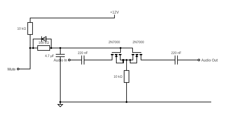
I found the basic circuit at https://g4tgj.github.io/Audio-Switch/.
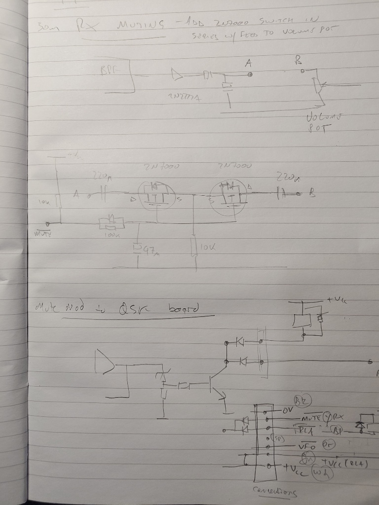
For the muting I hold the mute line high with 10k in the receiver and then the mute input is a “ground to mute” connection which is easily arranged from the TX QSK board.
It works well enough to both save my hearing and to provide a useful sidetone from the receiver during transmit, which means I don't need to add a sidetone circuit.
Mute clicks & thumps
I found this arrangement of using diodes to “share” the pull-down transistor switch with the c/o relay in the 30m TX Blog post about TX to perform poorly after I'd used it for a while and realized it needed a bit of a tweak to make it “right” rather than “okay”.
I noticed a loud click/thump as the first CW character was sent and the mute operated. Initially I assumed that the MUTE wasn't operating soon enough, or that the QSK wasn't delaying the SI5351 VFO enable line sufficiently long enough to allow the MUTE (and C/O relay) switching. Much probing with the 2-channel scope shows that the relative timing is okay. The loud initial click occurs whenever the first loud audio feeds into the mute circuit, regardless of how long the mute has been active, and how long the RF is delayed. I played with the Arduino code to delay the RF enable so that the RF didn't come on until 100mS after the MUTE and Relay c/o - enough to miss several morse characters - and yet still there was a loud click when the first loud audio arrived.
I tried pulling the MUTE line down to ground with a croc-clip-lead - and this cured the problem.
Looking at the MUTE line on a scope shows that it normally only goes down to about 1V when the transistor switches, not 0V and this leads to an initial loud click when the first loud audio arrives on first key-down. Once the click is gone the mute behaves correctly, but it appears that unless the MUTE line is hard-down it doesn't fully mute until a few mS after the first audio comes on the input to the SD7000.
Sharing the MUTE line via a single transistor switch and steering diodes was the problem.
The cure was to use a separate 2N3904 transistor to pull the MUTE line down hard without a diode inline.
Now the MUTE operates correctly, and smoothly and the faint leak-through is enough to act as a simple sidetone. And no loud CLICK on key down.
RX Bandpass Filter
Initially I installed a simple 2-stage Op Amp BPF. It was designed several years ago and I don't know what my though process was at the time - what Q and Gain I was aiming for. It's not bad but it's not as good as I would like it to be.
I had a look at the component values and reverse engineered the design.
With R1 = 47k, R2 = 6k8, R3 = 68k and the capacitors 10n it seems that the design Q was only 1.7 and the gain 0.7 and center frequency 800Hz . With two identical stages this would mean a designed overall gain of about 0.5.
I'm sure it could/should be better.
I redesigned for Q = 4 & Gain = 1.1 and Frequency = 700Hz, keeping the 10n capacitors
- R1 = 82k
- R2 = 2k7
- R3 = 180k
I breadboarded this to test and it gives a Q and gain just less that 1 with much better shape and attenuation of HF signals.
I then re-designed again for Q = 5 and got from memory
- R1 = 100k
- R2 = 2k
- R3 = 220k
This was slightly tighter and works nicely on the bench fed from a signal generator, measuring output on a 'scope. Next I need to build it on veroboard and install it in the RX and compare the performance.
Further Information
Page created : 16/07/26 22:57 BST
Page updated : 28/07/26 14:23 BST


Discussion